

On two occasions I have been asked, ‘Pray, Mr. Babbage, if you put into the machine wrong figures, will the right answers come out?’ […] I am not able rightly to apprehend the kind of confusion of ideas that could provoke such a question.
Charles Babbage, Passages from the Life of a Philosopher (1864)
Nowadays, in most realms, data reigns supreme. Data is used in various ways to improve decision-making, optimize operations, and drive growth, so finding the right approach to its storage and processing is crucial. Fortunately, database normalization can help with that, offering strategies to make your data well-structured, normalized, and safe to use.
What Does It Mean to Normalize a Database?
Normalizing a database refers to structuring it specifically and optimizing its efficiency and accuracy, as it was first proposed by Edgar F. Codd. There are different levels of database normalization, with increasing complexity.
The final goal of database normalization is to find a balance that minimizes redundancy while maintaining a convenient structure for specific purposes.
Why Is Database Normalization Important?
Imagine a database designed without normalization as a messy desk drawer. You throw everything in – receipts, keys, phone numbers – all mixed. Finding something specific becomes a frustrating hunt.
Normalization is like organizing that drawer. It creates a system for storing the data efficiently and accurately. Here’s why it’s crucial for database design:
- Reduces Redundancy: By organizing data strategically across tables, normalization minimizes the repetition of information. It saves storage space and eliminates the possibility of inconsistencies arising from duplicated data.
- Minimizes Errors: When data is scattered across tables, updates to a specific value might need to be made in multiple places. Normalization prevents this by ensuring each data point is stored only once. It reduces the likelihood of errors introduced during updates.
- Improves Performance: Normalized databases allow for more straightforward and efficient data retrieval. Since data is well-organized and related through defined connections, queries can target specific information without unnecessary processing.
- Improves Data Integrity: Normalization safeguards data from anomalies, which are inconsistencies that can occur when data is dependent on other data in unpredictable ways. It ensures the data accurately reflects reality.
- Simplifies Database Maintenance: As the database grows, changes become easier with normalization. Adding new data types or modifying existing ones is more straightforward in a well-structured system.
To make a long story short, the normalization keeps the database clean and organized, making it easier to manage, maintain, and use effectively with less effort.
Glossary
Before diving deeper into the database normalization processes, defining some specific terminology is important.
| Terminology | Description |
| Attribute | A property of some entity, also called a table field |
| Tuple | A set of interconnected valid attribute values that describe some entity together. It is presented as a table row or a table record in relational databases |
| Relation | A data structure that consists of a heading with entity attributes definition and an unordered set of records that share the same type. In relational databases, it is presented as a table |
| Primary key | An attribute or a collection of attributes in one table that’s distinctive for each record. It means the primary key can uniquely identify the record |
| Non-primary attribute | An attribute that is neither a primary key nor a part of a combined key |
| Foreign key | An attribute or a collection of attributes in one table that refers to another table’s primary key |
What Are Normal Forms?
The first important part of database normalization is based on the concept of normal forms. Normal form is a set of requirements for an entity to reduce data redundancy.
According to Codd’s idea, during normalizing, the entity data structure will gradually transform from one normal form to another by fulfilling certain requirements, each of which complements the previous ones and gives the relationship between data additional qualities.
First Normal Form (1NF)
The First Normal Form requires the representation of data in the form of relations built based on named attributes and their values in compliance with the following rules:
- Relation records data and attribute names don’t have repetitions
- The arrangement of relation records and attributes in the relation heading doesn’t matter since it doesn’t give any useful information
- Every attribute value in relation is elementary for its data type
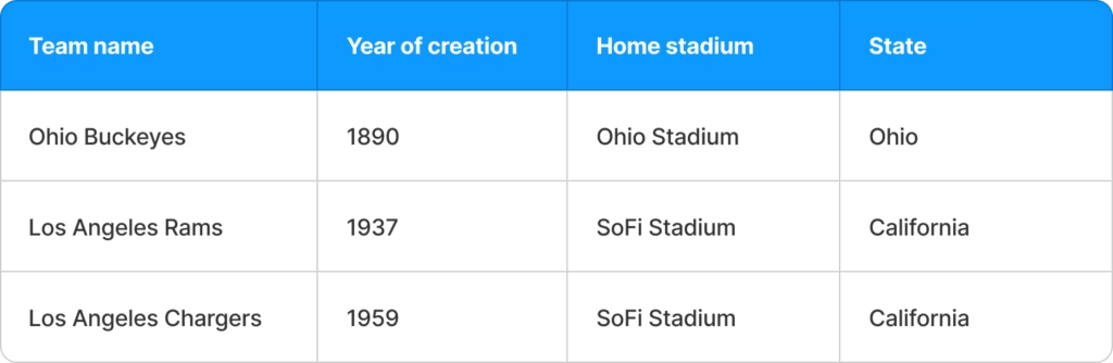
For example, let’s consider the following relation with football team creation dates:
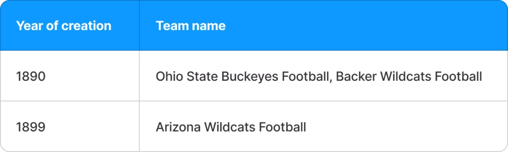
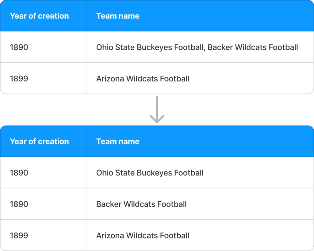
In this relation, the third rule of the First Normal Form is violated, since the record with the team created in 1890 contains two football team names. Let’s split this record into two rows to convert this relation into the first normal form.
Second Normal Form (2NF)
Relation in the Second Normal Form should fulfill the requirements of the First Normal Form and define a primary key on which the rest of the non-primary attributes of a record functionally depend.
Functional dependence between attributes means that some attributes, depending on attribute “A” will always have the same values for the same value of the “A” attribute. This concept fits well with the usage of primary keys – we have a unique and unrepeated record for each unique identifier.
An important point is that the primary key may include several attributes called a combined key. Considering this, existing attributes that functionally depend only on some attribute of the combined key will violate the Second Normal Form requirements.
For example, take a look at the following table describing football games:
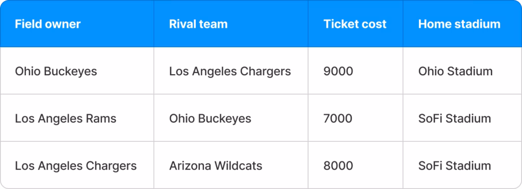
This relation is in the First Normal Form but violates the Second Normal Form requirements. It happens because this relation has a combined primary key that consists of the “Field owner” and the “Rival team” attributes to describe some football games.
The “Ticket cost” attribute depends on this primary key, but the “Home stadium” attribute depends only on the “Field owner”. Although the “Field owner” attribute is a part of the primary key, such a relationship between the “Home field” and the “Field owner” attributes violates the rule about functional dependency on the single primary key.
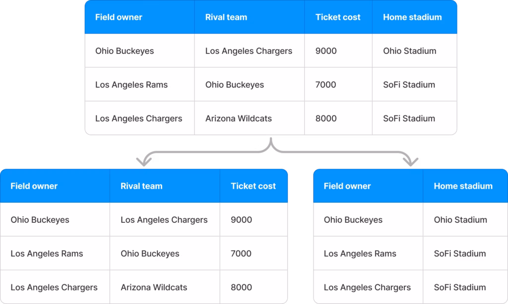
This issue may be resolved by creating two separate relations – “Teams” featuring descriptions of their home stadiums and “Games” containing information about football games.
Third Normal Form (3NF)
Relation in the Third Normal Form should fulfill the requirements of the Second Normal Form and not have attributes that functionally depend on other non-primary attributes of this entity, even if this non-primary attribute depends on the primary key.
Such a relationship, when some property depends on the primary key only through another property, is called a transitive dependency. Considering this, the Third Normal Form requires a lack of transitive dependencies for non-primary attributes.
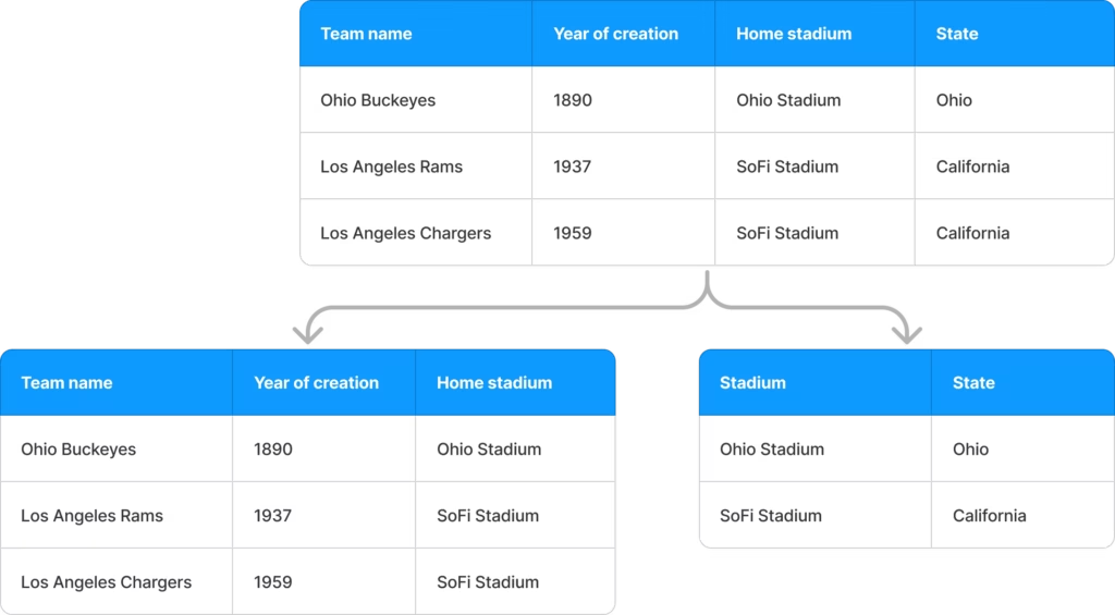
For example, we have the following relation, which describes football teams and their placement:
This relation is in the Second Normal Form. Still, it violates the Third Normal form requirements since the “State” attribute depends on the non-primary “Home stadium” attribute, while the rest of the attributes, including the “Home stadium”, are related to the “Team name” as a primary key.
To resolve it, we need to move the data that depends on non-primary attributes into a separate table, so we will get the “Teams” and “Home Fields” relations:
Boyce-Codd Normal Form (BCNF)
The Third Normal Form doesn’t cover cases when a relation has several primary key candidates, especially if candidate keys consist of multiple attributes, some of which are common for these candidate keys. The Boyce-Codd Normal Form is implemented to prevent data anomalies in such cases.
Cases when there are several key candidates and data partially dependent on each of them are called non-trivial dependencies. It means that the dependency between attributes might be difficult to define according to the relation context.
So, functional dependency is trivial when we can define only one primary key, and each non-primary attribute should fully and non-transitively functionally depend on it.
The Boyce-Codd Normal Form is a specific case of the Third Normal Form, so the relation in the BCNF should fulfill the Third Normal Form requirements, and each attribute is trivially functionally dependent on only one primary key.
Let’s proceed with the example of the employee mood statistics from an HRM system.
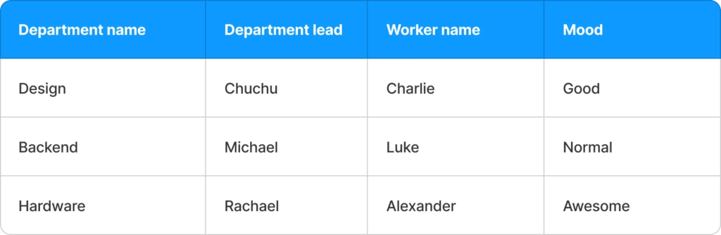
This table has several primary key candidates. Firstly, it may be the set of “Department name”, “Department head” and “Worker name” attributes, but this candidate key is ambiguous since it may be shortened to a pair of “Department name” and “Worker name” attributes or “Department head” and “Worker name” attributes. All candidate keys have a common attribute – “Worker name”, making such a relationship non-trivial.
As you can see, there is a bit of difference with the Third Normal Form since in the case of the 3NF there are some transitive dependencies on non-primary attributes, though all attributes depend on the primary key candidate. Still, we can’t define concrete functional dependency due to a common attribute in the different primary key candidates.
Let’s split this relation into the “Departments” and “Moods” relations to resolve this problem:
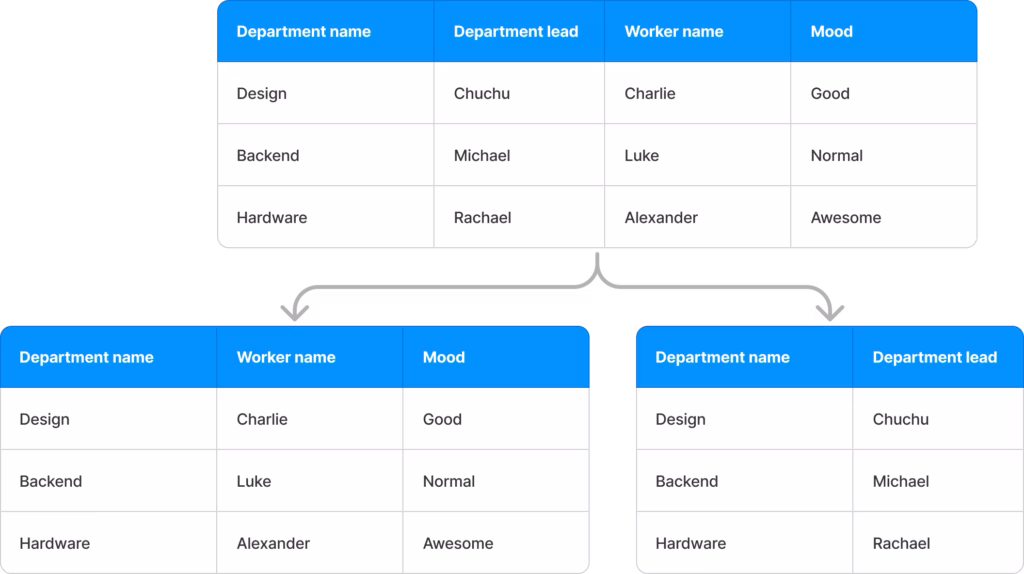
In cases, when the relation has only one primary key all non-primary attributes functionally depend on, the Third Normal Form is the Boyce-Codd Normal Form.
What Are Entity Relationships?
Another important aspect of database normalization is the concept of entity relationships. This concept describes the relationship between each pair of entities in the system. There are three classes of relationships between entities in relational databases. Importantly, in all classes of relationships presented below, any entity in the pair may be mandatory or optional for the other.
One to One (1:1)
In this class of relationship, each separate record in the entity’s table may be related only to one record from another entity’s table. At the same time, each separate record from the second entity’s table may be related only to one table from the first entity’s table.
One to Many (1:N)
In one-to-many relationships, each single record of the first entity’s table may be related to several records from the second entity’s table. At the same time, several records from the second entity’s table may be related to the same record from the first entity’s table.
Many to Many (N:M)
In such relationships, each record from both entities’ tables may be related to several records in the other table.
Entity-Relation Diagram
The relations between entities are often described with an entity-relation diagram, so before investigating a specific entity relationship, let’s learn the ropes on how such diagrams work.
An entity-relation diagram is a set of figures that helps us understand how entities are related to each other.

It consists of the following parts:
- A rectangular figure is used to define an entity. Each entity in the diagram will be a rectangle.
- A rhombus figure is used to explain the relation between a pair of entities.
Next to an entity’s rectangle, we can see a digit “1” or a letter “N” (it may be any letter or sign). According to the class of relationship presented above, the digit “1” next to the entity indicates that each record from the opposite entity may be related only to one record of this entity.
In this example, we can see that 1 is placed next to a Gallery entity. It means that each record from the Picture entity’s table may be related only to one record from the Gallery entity’s table.
Similarly, a letter “N”, placed next to an entity, indicates that every single table record of the entity on the opposite side of the relationship may be related to any number of this entity. Based on the example above, we can see that every single record of the Gallery entity may be related to any number of the Picture entity records.
The next element of this diagram is a dot placed inside the entity’s rectangle. This dot indicates that this entity is mandatory for the entity placed on the opposite side of the rhombus. Absence of a dot inside the entity’s rectangle indicates that this entity is optional for the entity on the opposite side of the diagram.
As we can see from the diagram above, the Picture entity is optional for the Gallery entity, since the Gallery may exist without storing any pictures. However, the Gallery is mandatory for the Picture since a picture should be stored somewhere else.
In the bottom line, the class of this relationship is one-to-many (1:N), where the N-relational entity is optional for the 1-relational entity.
Entity-Relationship Normalization
One-to-one, where both entities are mandatory
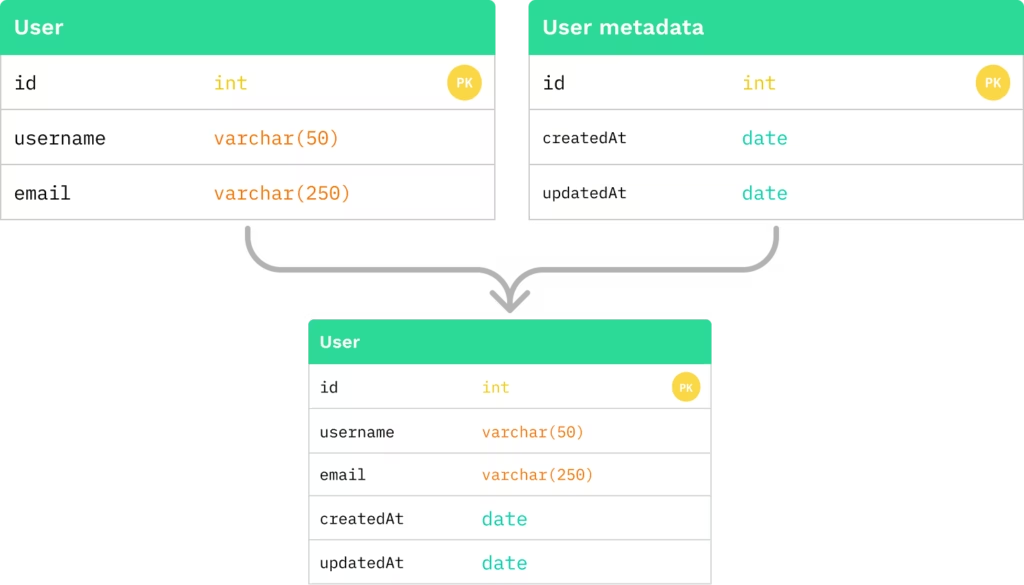
For a one-to-one relationship, where both entities are mandatory for each other, a single entity is created. Also, in this case, we can use any initial entity’s primary key as the primary key of a new entity.
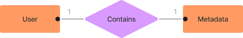
As we can see, the User entity should always contain some Metadata, while Metadata should always be connected to the entity it describes. Since a class of relationships between these entities is one-to-one, we can combine them into a single entity.
One-to-one, where only one entity is mandatory
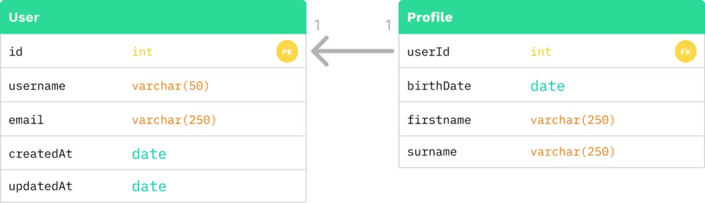
For a one-to-one relationship, where only one of the entities is mandatory for the other, two separate tables are created. To describe the connection between these entities, we need to add a foreign key that will refer to the primary key of the mandatory entity to the optional entity.

In this example, the User entity is mandatory for the Profile entity since Profile can’t exist without a user, but the Profile is optional for the User since, for example, the user can skip the step of filling additional data during the registration process, and in this case Profile record may not be created for them. From the perspective of the entity tables, it will look as follows:
One-to-one, where both entities are optional
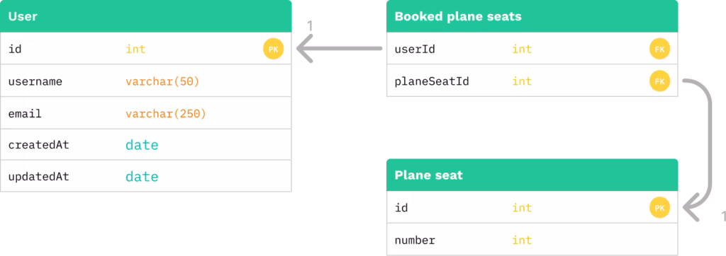
For a one-to-one relationship where both entities are optional, three separate tables are created – two tables for each initial entity, and the third one for the connection between them. This third table will contain two foreign keys, which will refer to the primary keys of the initial entities.

For example, there is a booking system that allows Users to book a seat on a plane. For some flights, not all places in the plane may be booked, which makes a Plane seat entity optional for the User, and, at the same time, it makes the User entity optional for a Plane seat entity, since if the plane seat is free, there are no passengers assigned to it.
One-to-many, where an N-relational entity is mandatory
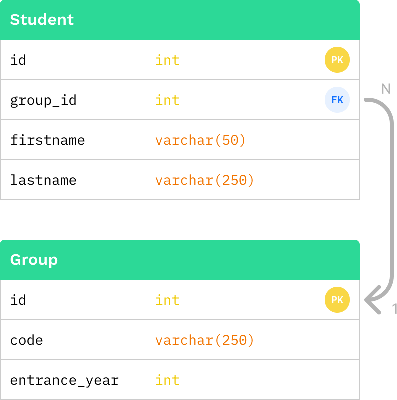
For a one-to-many relationship where an N-relational entity is required, two tables are formed, and the primary key of the 1-relational entity should be added as a foreign key to the N-relational entity.

In this example, we have Students and Groups. A group can’t exist without at least one student, so it is mandatory for the Student. At the same time, students can’t study at the University without being assigned to a Group, so the Group is also mandatory for students. Also, a Student may be a member of only one of the Groups, while a Group may include a lot of students. In this case, a relationship class will be one-to-many, where an N-relational entity is mandatory for a 1-relational entity.
One-to-many, where the N-relational entity is optional
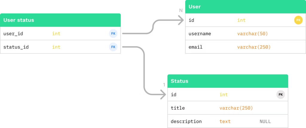
For a one-to-many relationship, if the N-relational entity is optional, three entity tables are created – two tables for each of the initial entities, and the third one for the connection between them. This third table will contain two foreign keys, which will refer to the primary keys of the initial entities.
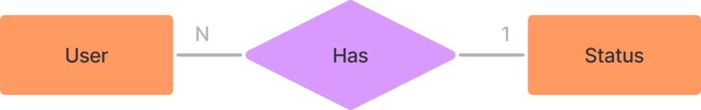
In this example, we have a social network system that allows users to set a status from a predefined list. A user can have a status, but they can also use a system without setting any statuses, so the Status entity is optional for the User. The user can set only one status at a time. From the Statuses side, each Status can be selected by several users, but some of the statuses can not be selected, which makes the User entity optional for the Status. As a conclusion, we have a one-to-many relationship, where both entities are optional for each other. What’s important, only the N-relational entity is optional for the 1-relational entity.
Many-to-many relationship
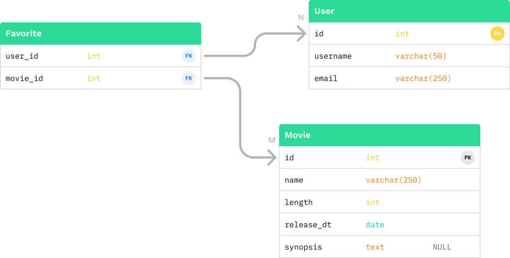
For a many-to-many relationship, three entity tables are always created – two tables for each of the initial entities and the third one for the connection between them. This third table will contain two foreign keys, which will refer to the primary keys of the initial entities.

In this example, we have a User’s favorite movies list. A user can have several favorite Movies on the one hand, and, on the other hand, the same Movie can be in the favorite list for a lot of Users. That makes this class a many-to-many relationship. In most cases, entities in many-to-many relationships are optional to each other, but in the scope of entity-relationship normalization, it doesn’t matter.
Let’s Proceed with an Example
Imagine we have a system to manage artworks and places where they are stored. Before implementation, our Business Analyst investigated the market and defined the following entities and their properties as important for our system:
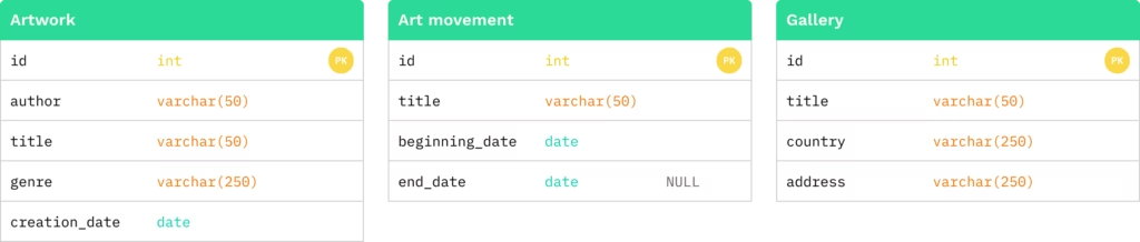
At first sight, it looks pretty normal, but several data redundancy problems are revealed.
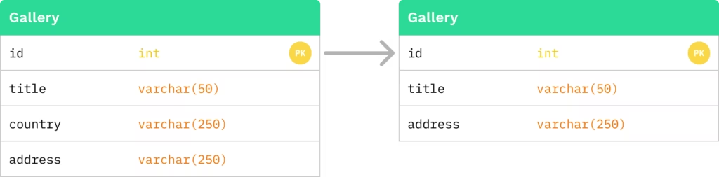
First of them – the Address and the Country entities together create data redundancy, which breaks the first rule of the First Normal Form. For this system, we can save the information about the country where the gallery is placed, inside the address property, and it will allow us to avoid data redundancy.
To resolve this issue, let’s remove the country property from the Gallery entity.
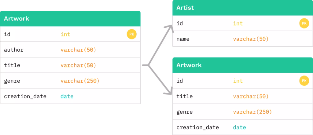
The second problem is a transitional dependency between the Artwork author and the rest of the Artwork properties, which violates the Third Normal Form rules. If we don’t fix this issue, the Artworks with several authors will require the creation of several records for the same Artwork, each differing only by the author, which will cause a lot of data duplication.
To resolve this issue, we need to create a separate table for transitive dependencies – in this case, for the Author – and remove these transitive dependencies from the initial entity. Let’s name the new entity as an Artist.
After we normalized existing entities according to the Normal Forms, let’s determine the relationships between these entities.
Relationship between an Artwork and an Author
- An artist can have many works
- A group of artists can make a picture
- There must be at least one author in the picture
- The artist may not have an artwork (e. g. they are still studying)

As a result, we can define relationships between this pair as many-to-many, where the Artist is mandatory for the Artwork, while the Artwork is optional for the Artist. To describe this relationship, three tables will be created.
Relationship between an Artwork and an Art movement
- The art movement can include many artworks
- An art movement without artworks can’t exist
- The picture necessarily belongs to at least one art movement
- The picture can belong to several art movements at the same time

In this case, we also have a many-to-many relationship for a pair of Artwork and Art movement entities. Both entities are mandatory for each other, since they are very closely related. For this pair, three tables will be created as well.
Relationship between an Artwork and a Gallery
- The Artwork must be stored in the Gallery
- The Gallery may not contain Artworks
- The Gallery may contain a lot of Artworks

For Artwork and Gallery entities, we have a one-to-many relationship, where the N-relational entity – Artwork – is optional for the 1-relational entity – Gallery. It happens, since the Artwork may be stored in only one gallery at the same time, but the Gallery can contain a lot of artworks, as well as none of them. For this relationship, only two entities will be created –- one for Artwork and one for Gallery. Also, according to such a relationship, we need to add a foreign key, which will refer to the Gallery primary key, into the Artwork entity.
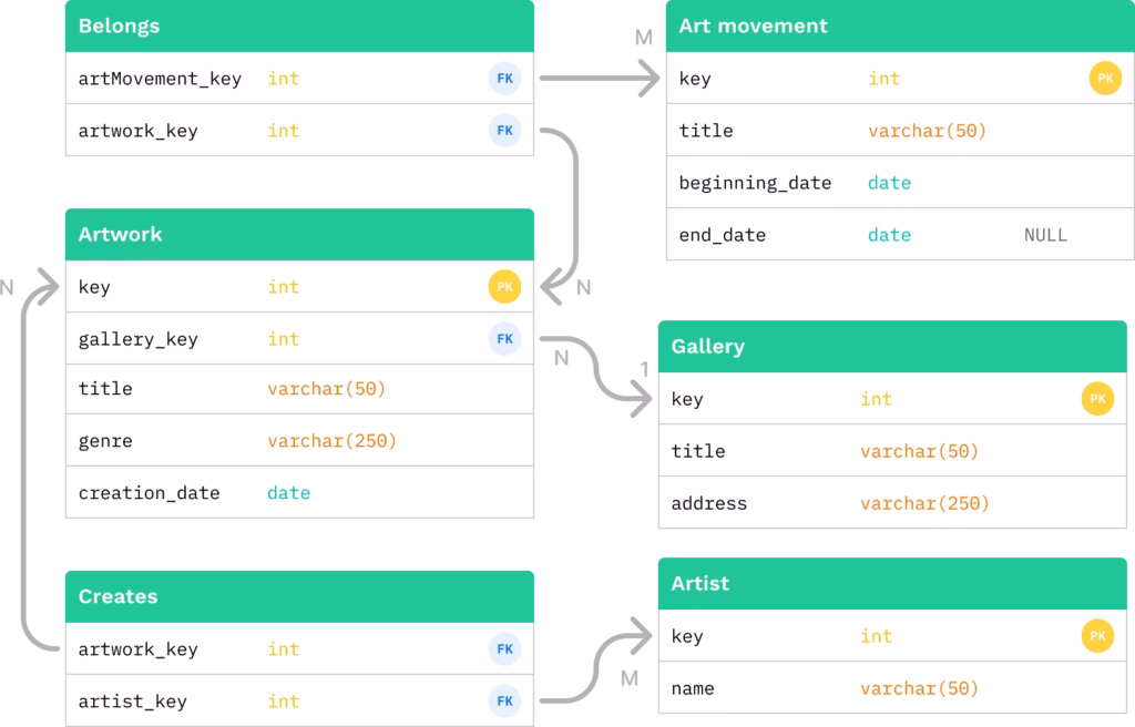
The final ER diagram for all entities will look in the following way.
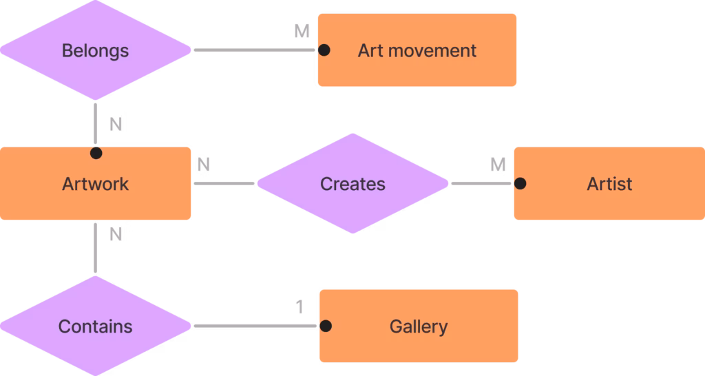
As we can see, it doesn’t contain any new information, just composes all relationships into a single diagram, which makes it easier to translate it to the entity tables.
That’s it. Each of the system’s entities was normalized to avoid data redundancy, as well as relationships between the system’s entities to prevent anomalies on reading or modifying the data inside the system. Repeating all steps above, we can add more entities or remove some of them, and be sure that despite such modifications, our data is safe and easy to maintain.
Afterword
This article contains only some basics about the process of database normalization, but I hope this information will be useful for you and will help you create stable and scalable systems with relational databases. Good luck in your journey in the Information Technologies world!
Check out our blog to get more technical insights.
If you are looking for a reliable JavaScript development partner, explore our JavaScript Development Services!


